Types Of Tensile Structures - SKengineers
Types of Tensile Structures -

A tensile structure is a construction of elements carrying
only tension and no compression or bending. The term tensile should not be
confused with tensegrity, which is a structural form with both tension and
compression elements. Tensile structures are the most common type of thin-shell
structures.
Most tensile structures are supported by some form of
compression or bending elements, such as masts (as in The O2, formerly the
Millennium Dome), compression rings or beams.
A tensile membrane structure is most often used as a roof,
as they can economically and attractively span large distances. Tensile
membrane structures may also be used as complete buildings, with a few common
applications being sports facilities, warehousing and storage buildings, and
exhibition venues.
The classification of tensile structures are made on the
plane in which the tensile forces are acting in the structure. On this basis,
the tensile structure are divided into following types.
1. Linear Tensile Structures -

Linear tensile structures are the structure in which the all
the member are in linear tensile forces. This linear members are supported by
the compression members , but the major loads are carried out by tensile
members. Common example of these structure is cable suspended bridges. The main
pillars acts as compression members, but the whole load is carried out by the
cables which are in tension.
Tensile forces acting on suspended bridge.
Linear
tensile structures are further classified into following types,
Suspension bridges -

A typical suspension bridge is a continuous girder
suspended by suspension cables, which pass through the main towers with the aid
of a special structure known as a saddle, and end on big anchorages that hold
them. Fig. 1.26 shows the essential structural members and elements of typical,
including tower, hanger, main girder, and the anchorage. The main forces in a
suspension bridge are tension in the cables and compression in the towers. The
deck, which is usually a truss or a box girder, is connected to the suspension
cables by vertical suspender cables or rods, called hangers, which are also in
tension. The weight is transferred by the cables to the towers, which in turn
transfer the weight to the anchorages on both ends of the bridge, then finally
to the ground. The curve shape of the suspension cables is similar to that of
arch. However, the suspension cable can only sustain the tensile forces, which
is different from the compressive forces in the arch. Also because of this, the
cable will never “buckle” and highly efficient use of high strength steel
materials becomes possible. The use of suspension bridges makes longer main
spans achievable than with any other types of bridges, and they are practical
for spans up to around 2 km or even larger. The top 10 largest suspension
bridges in the world are listed in Table 1.4. The Akashi Kaikyō Bridge (Fig.
1.27) crosses the busy Akashi Strait and links the city of Kobe on the mainland
of Honshu to Iwaya on Awaji Island, in Japan. Since its completion in 1998, the
bridge has had the longest central span of any suspension bridge in the world
at 1991 m. The central spans of the top 10 largest suspension bridges are
longer than 1300 m, indicating the incomparable spanning capability of this
bridge type. The suspension bridge will be discussed in detail in Chapter 11.
Table 1.4. List of Longest Suspension Bridges
Rank Name Main Span (m) Year Opened Location Country
1 Akashi
Kaikyō Bridge 1991 1998 Kobe-Awaji
Island Japan
2 Xihoumen
Bridge 1650 2009 Zhoushan China
3 Great
Belt Bridge 1624 1998 Korsør-Sprogø Denmark
4 Yi
Sun-sin Bridge 1545 2012 Gwangyang-Yeosu South Korea
5 Runyang
Bridge 1490 2005 Yangzhou-Zhenjiang China
6 Nanjing
Fourth Yangtze Bridge 1418 2012 Nanjing China
7 Humber
Bridge 1410 1981 Hessle-Barton-upon-Humber United Kingdom
8 Jiangyin
Bridge 1385 1999 Jiangyin-Jingjiang China
9 Tsing
Ma Bridge 1377 1997 Tsing
Yi-Ma Wan Hong Kong
10 Hardanger
Bridge 1310 2013 Vallavik-Bu Norway
Draped cables -

Cable-stayed beams or trusses -

Cable trusses -

Truss and cable elements are defined by their ability to
carry solely axial loads. Nonetheless, since cables have no stiffness when
loaded in compression, they function only in tension. Moreover, cables are
typically pre-tensioned, i.e., they carry an initial tension load, while truss
elements are, typically, not pre-tensioned. This pre-tension force
substantially differentiates the behavior of the two elements.
Example -
A truss and a cable of the same length (L), cross-section (A), and elasticity modulus (E), as shown in Figure 1, are subjected to a horizontal force, F. The cable is pre-tensioned by a force, T. Both the truss and the cable are anchored to the ground in both ends, and the upper end is free to move laterally. The lateral force, F, results in a horizontal displacement, δ.
Straight
tension cables -
2. Three-dimensional Tensile Structures -

Three-dimensional tensile structures, is a compilation of
elements that are primarily in tension, with the compression being transferred
to a central mast and down into the ground.
The most common occurrence of three-dimensional tension can be seen at
sports arenas and usually serve as roofs for these structures.
Tensegrity Tensile Structures
Three-dimensional tensile structures are further classified into following types,
Bicycle wheel (can be used as a roof in a horizontal
orientation)
3D cable trusses
Tensegrity structures
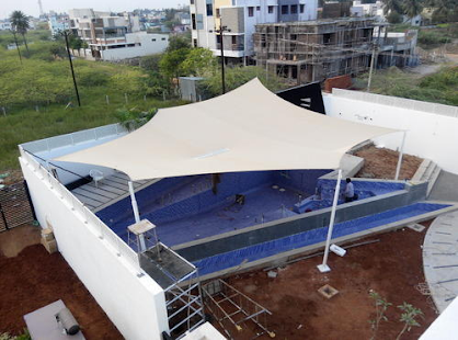
3. Surface-Stressed Tensile Structures -

Surface-stressed tensile structures are same as other 2
tensile structure, but the surface members are tension bearing members. Fabric
tensile structures are the great examples of Surface-stressed tensile
structures, where the vertical pillars hold the special deisgned fabric which
is in tension.
Fabric Tensile structure
Surface-Stressed tensile structures are further classified into following types,
Fabric structure
Prestressed membranes
Pneumatically stressed membranes
Gridshell
Shapes of
Tensile Structures -
The four basic shapes used in the tensile structures are,
1. Conical Tension Structure -

Highly effective for covering large areas, a conical tension
structure is easily identified by its tent-like shape. Conical designs can
feature either single or multiple masts. For both design options, membranes are
tensioned between a ring at the pinnacle and the lower perimeter support
columns. Cones are especially effective in areas that need to comply with high
rain or snow load regulations.
Conical Tension Structure
2. Hyper or Anticlastic Structure -

As one of the most common of all tensioned membrane
structures due to its aesthetically pleasing look, hypar (hyperbolic
paraboloid) shapes are notable for their excellence with shape retention and
water runoff. These structures rely on two opposing curvatures, also known as
anticlastic, for their stability. This type of structure is ideal for shade
over seating areas or high traffic walkways.
Hypar or Anticlastic Structure
3. Parallel Arch or Barrel Vault Structure -

These symmetrical curved parallel arch designs form an
incredibly functional tensioned membrane canopy that can span long distances
such as a sports arena or smaller areas such as an entryway. Depending on the spans, a barrel vault system
can be a very cost-effective way to incorporate tensile membrane on a project
due to the repetitive nature of the design and efficiencies of materials.
4. Cable Net & Membrane Structure -


For long-span tensile membrane roofing applications
typically found in stadiums or large spaces, 3D cable net or cable grid
structures are an efficient solution for lightweight tensile architecture.
Cable
material E (GPa) UTS (MPa) Strain at 50% of UTS
Solid
steel bar 210 400–800 0.24%
Steel
strand 170 1550–1770 1%
Wire rope 112 1550–1770 1.5%
Polyester
fibre 7.5 910 6%
Aramid
fibre 112 2800 2.5%
Advantages
of Tensile Structures -
With proper construction methodologies in place by
design-build specialty contractors for tensile architecture, the installation
of tension membrane structures is often faster and more cost-effective in
comparison to traditional construction projects.
Because of the translucency associated with nearly all of
the fabric options, tensile fabric building structures provide an abundance of
daytime light underneath, making it an inviting and comfortable space below.
In addition to being more weather-proof and lighter in
weight than sticks and animal skins, modern fabrics offer advantages such as
protection from ultraviolet (UV) radiation and greater wind resistance. They
are also coated with materials that resist UV degradation.
Due to the unique flexible characteristics of the fabric
membrane, tensioned membrane structures allow architects, designers, and
engineers the opportunity to experiment with form and create visually exciting
and iconic structures.
When looking to cover large areas of space, the light weight
nature of membrane is a cost-effective solution for long span applications
while allowing for the possibility of column-free space. As a result, tensile
membrane requires less structural steel supports compared to traditional
building products, ultimately reducing project costs for building owners.
The weight of the membrane in tensile structures is very
less and consequently, the quantity of structural steel utilized to support the
membrane is also minimal. Thus, the weight, as well as the overall cost of
tensile structures is much less as compared to conventional roofing systems. As
stainless steel is utilized, more useful space free of columns becomes
available. As the weight of the structure is so little, it will not experience
much acceleration forces under seismic action.
The membrane material itself can withstand within the range
of -40 o C to +70 o C. Companies of warranty for their fabrics and usually the
minimum life span of these structures is about 25 years.
The erection of the tensile structures takes less than a
week to complete as all the patterning & fabrication works are mostly
carried out in warehouses and the structure is erected on site. The
construction period is only the time required for its erection, which can be
reduced to a minimum by using advanced construction equipment and techniques.
Conclusion
-


Comments
Post a Comment