What Is Hydraulic Pumps? How It Works? - SKengineers
WHAT IS HYDRAULIC PUMPS? HOW IT WORKS?

A hydraulic pump converts the mechanical energy from the
prime mover into hydraulic energy for use by the system. Hydraulic energy is
the combination of pressure and flow required by the actuators to perform
useful work. It is important to understand that hydraulic energy is both
pressure and flow combined, because one without the other cannot achieve work.
Pressure would just consist of trapped fluid and flow would have no energy to
move fluid alone.
A hydraulic pump pushes on fluid, and in this regard, fluid can be considered a solid as it is transmitted throughout the machine and then pushes on actuators to eventually move loads. Motion control professionals will have me point out that oil is compressible, but that’s a discussion for another blog. The point is that a pump could be pushing on sand, ball bearings or any other solid medium capable of taking the shape of its container, and the result would still be the transmission of force.
Transmission of force is really the name of the game with
hydraulics, and is the basis for Cosford’s Law, which states that “pressure
makes it go, flow is just the rate in which you can create pressure.” For fluid
to be moving, pressure must absolutely be highest at the pump; always. This
flies in the face of the fallacy that pressure is resistance to flow. Pressure
will rise as high as it needs to be to overcome downstream resistance, but if
it didn’t start at the pump, fluid would move backwards.
Pressure in hydraulics is the result of Newton’s Third Law of Motion, that every action has an equal and opposite reaction. The opposing force can be a loaded cylinder or a flow control, and the pump doesn’t care which. It will continue to push the fluid as pressure rises to overcome resistance, even if it results in something blowing up or the prime mover being overloaded.

Flow from a pump is a function of displacement (volume) and
speed. A larger pump can push more fluid at once, or by spinning a pump faster,
it will push on fluid more often. Just like in the world of electrons, where
power is a combination of voltage and amperage, power in hydraulics is a
combination of pressure and flow. By doubling pressure while leaving flow the
same, horsepower is doubled. Also, by doubling flow while leaving pressure the
same, horsepower is also doubled.
Understanding the operation of a hydraulic pump will do
volumes (no pun intended) for your understanding of fluid power. When you
realize all energy starts at the pump, you can better design or troubleshoot
any system.
TYPES OF
HYDRAULIC PUMPS -
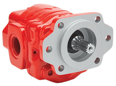
GEAR PUMPS -

For truck-mounted hydraulic systems, the most common design
in use is the gear pump. This design is characterized as having fewer moving
parts, being easy to service, more tolerant of contamination than other designs
and relatively inexpensive. Gear pumps are fixed displacement, also called
positive displacement, pumps. This means the same volume of flow is produced
with each rotation of the pump’s shaft. Gear pumps are rated in terms of the
pump’s maximum pressure rating, cubic inch displacement and maximum input speed
limitation.
Generally, gear pumps are used in open center hydraulic
systems. Gear pumps trap oil in the areas between the teeth of the pump’s two
gears and the body of the pump, transport it around the circumference of the
gear cavity and then force it through the outlet port as the gears mesh. Behind
the brass alloy thrust plates, or wear plates, a small amount of pressurized
oil pushes the plates tightly against the gear ends to improve pump
efficiency.
FEATURES
-
Most common design
Fewer moving parts, easy to service, more tolerant of
contaminates, relatively inexpensive
Fixed, also called positive, displacement pumps
Rated in terms of max pressure rating, cubic inch
displacement, max input speed limitation
Used in open centre hydraulic systems
Transports oil around circumference of gear cavity and
forces it through outlet port
Encompasses thrust plates that push against gear ends with
small amount of pressurized oil to improve pump efficiency.
PISTON PUMPS -

When high operating pressures are required, piston pumps are
often used. Piston pumps will traditionally withstand higher pressures than
gear pumps with comparable displacements; however, there is a higher initial
cost associated with piston pumps as well as a lower resistance to
contamination and increased complexity. This complexity falls to the equipment
designer and service technician to understand in order to ensure the piston
pump is working correctly with its additional moving parts, stricter filtration
requirements and closer tolerances. Piston pumps are often used with
truck-mounted cranes, but are also found within other applications such as snow
and ice control where it may be desirable to vary system flow without varying
engine speed.
A cylinder block containing pistons that move in and out is
housed within a piston pump. It’s the movement of these pistons that draw oil
from the supply port and then force it through the outlet. The angle of the
swash plate, which the slipper end of the piston rides against, determines the
length of the piston’s stroke. While the swash plate remains stationary, the
cylinder block, encompassing the pistons, rotates with the pump’s input shaft.
The pump displacement is then determined by the total volume of the pump’s
cylinders. Fixed and variable displacement designs are both available.
FEATURES
-
Withstand higher pressures
Higher initial cost, lower resistance to contamination and
increased complexity
Additional moving parts, stricter filtration requirements
and closer tolerances
Truck-mounted cranes
Good when desirable to vary system flow without varying
engine speed
Fixed and variable displacement designs available
Encompasses cylinder block containing pistons that move in
and out – this movement draws oil from the supply port and forces through the
outlet
Angle of swash plate determines the length of the piston’s
stroke
Swash plate remains stationary.
Displacement determined by total volume of pump cylinders.
FIXED
DISPLACEMENT -
With a fixed displacement piston pump, the swash plate is
nonadjustable. Its proportional output flow to input shaft speed is like that
of a gear pump and like a gear pump, the fixed displacement piston pump is used
within open centre hydraulic systems.
VARIABLE DISPLACEMENT
As previously mentioned, piston pumps are also used within
applications like snow and ice control where it may be desirable to vary system
flow without varying engine speed. This is where the variable displacement
piston pump comes into play – when the hydraulic flow requirements will vary
based on operating conditions. Unlike the fixed displacement design, the swash
plate is not fixed and its angle can be adjusted by a pressure signal from the
directional valve via a compensator.
Should more flow be required, the swash plate angle changes,
increasing the pump displacement by creating a longer piston stroke. Contrary
to a fixed displacement piston pump, the variable displacement is used in a
closed centre system. With a closed centre system, the swash plate angle within
the variable displacement pump decreases as the flow requirement diminishes so
that there is no excess flow or loss of hydraulic horsepower.
Variable displacement piston pumps can be flow compensated,
pressure compensated or both flow and pressure compensated.
Flow
Compensated –
As flow requirements change, the swash plate angle is
adjusted to maintain a constant margin of pressure.
Pressure
Compensated –
Regardless of changes in system pressure, a specified flow
is maintained through adjusting the swash plate angle.
Flow and
Pressure Compensated Combined –
These systems with
flow and pressure compensation combined are often called a load-sensing system,
which is common for snow and ice control vehicles.
VANE PUMPS -

Vane pumps were, at one time, commonly used on utility
vehicles such as aerial buckets and ladders. Today, the vane pump is not
commonly found on these mobile (truck-mounted) hydraulic systems as gear pumps
are more widely accepted and available.
Within a vane pump, as the input shaft rotates it causes oil
to be picked up between the vanes of the pump which is then transported to the
pump’s outlet side. This is similar to how gear pumps work, but there is one
set of vanes – versus a pair of gears – on a rotating cartridge in the pump
housing. As the area between the vanes decreases on the outlet side and
increases on the inlet side of the pump, oil is drawn in through the supply
port and expelled through the outlet as the vane cartridge rotates due to the change
in area.
FEATURES –
Used on utility vehicles, but not as common today with gear
pumps more widely accepted and available
Input shaft rotates, causing oil to be picked up between the
vanes of the pump which is then transported to pump outlet side as area between
vanes decreases on outlet side and increases on inlet side to draw oil through
supply port and expel though outlet as vane cartridge rotates.
Screw pumps -

Screw pumps (fixed displacement) consist of two Archimedes'
screws that intermesh and are enclosed within the same chamber. These pumps are
used for high flows at relatively low pressure (max 100 bars (10,000
kPa)).[clarification needed] They were used on board ships where a constant
pressure hydraulic system extended through the whole ship, especially to
control ball valves[clarification needed] but also to help drive the steering
gear and other systems. The advantage of the screw pumps is the low sound level
of these pumps; however, the efficiency is not high.
The major problem of screw pumps is that the hydraulic
reaction force is transmitted in a direction that's axially opposed to the
direction of the flow.
There are two ways to overcome this problem:
put a thrust bearing beneath each rotor;
create a hydraulic balance by directing a hydraulic force to
a piston under the rotor.
Types of
screw pumps –
single
end
double
end
single
rotor
multi
rotor timed
multi
rotor untimed.
Bent axis
pumps
Bent axis pumps, axial piston pumps and motors using the
bent axis principle, fixed or adjustable displacement, exists in two different
basic designs. The Thomas-principle (engineer Hans Thomas, Germany, patent
1935) with max 25 degrees angle and the Wahlmark-principle (Gunnar Axel
Wahlmark, patent 1960) with spherical-shaped pistons in one piece with the
piston rod, piston rings, and maximum 40 degrees between the driveshaft center-line
and pistons (Volvo Hydraulics Co.). These have the best efficiency of all
pumps. Although in general, the largest displacements are approximately one
litre per revolution, if necessary a two-litre swept volume pump can be built.
Often variable-displacement pumps are used so that the oil flow can be adjusted
carefully. These pumps can in general work with a working pressure of up to
350–420 bars in continuous work.
Inline axial piston pumps -

axial
piston pump, swashplate principle -
By using different compensation techniques, the variable
displacement type of these pumps can continuously alter fluid discharge per
revolution and system pressure based on load requirements, maximum pressure
cut-off settings, horsepower/ratio control, and even fully electro proportional
systems, requiring no other input than electrical signals. This makes them
potentially hugely power saving compared to other constant flow pumps in
systems where prime mover/diesel/electric motor rotational speed is constant
and required fluid flow is non-constant.
Rotary
vane pumps -
Fixed
displacement vane pump -
A rotary vane pump is a positive-displacement pump that
consists of vanes mounted to a rotor that rotates inside a cavity. In some
cases these vanes can have variable length and/or be tensioned to maintain
contact with the walls as the pump rotates A critical element in vane pump
design is how the vanes are pushed into contact with the pump housing, and how
the vane tips are machined at this very point. Several type of "lip"
designs are used, and the main objective is to provide a tight seal between the
inside of the housing and the vane, and at the same time to minimize wear and
metal-to-metal contact. Forcing the vane out of the rotating centre and towards
the pump housing is accomplished using spring-loaded vanes, or more
traditionally, vanes loaded hydrodynamically (via the pressurized system
fluid).
Radial piston pump -
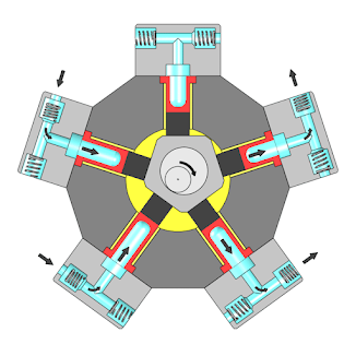
A radial piston pump is a form of hydraulic pump. The
working pistons extend in a radial direction symmetrically around the drive
shaft, in contrast to the axial piston pump.
CLUTCH PUMPS -

A clutch pump is a small displacement gear pump equipped
with a belt-driven, electromagnetic clutch, much like that found on a car’s air
conditioner compressor. It is engaged when the operator turns on a switch
inside the truck cab. Clutch pumps are frequently used where a transmission power
take-off aperture is not provided or is not easily accessible. Common
applications include aerial bucket trucks, wreckers and hay spikes. As a
general rule clutch pumps cannot be used where pump output flows are in excess
of 15 GPM as the engine drive belt is subject to slipping under higher loads.
FEATURES
-
Small displacement pumps
Belt driven
Aerial bucket trucks, wreckers and hay spikes
Limited to 15 GPM applications
DUMP PUMPS -

Of the different types of hydraulic pumps, the dump pump is
the most recognizable. This type of pump is commonly used in dumping
applications from dump trailers to tandem axle dump trucks. The dump pump is
specifically designed for one application – dump trucks – and is not suitable
for other common trailer applications such as live floor and ejector trailers.
What separates this pump from the traditional gear pump is
its built-in pressure relief assembly and an integral three-position, three-way
directional control valve. The dump pump is unsuited for continuous-duty
applications because of its narrow, internal paths and the subsequent
likelihood of excessive heat generation.
Dump pumps are often direct mounted to the power take-off;
however, it is vital that the direct-coupled pumps be rigidly supported with an
installer-supplied bracket to the transmission case with the pump’s weight at
70 lbs. With a dump pump, either a two- or three-line installation must be
selected (two-line and three-line refer to the number of hoses used to plumb
the pump); however, a dump pump can easily be converted from a two- to
three-line installation. This is accomplished by inserting an inexpensive
sleeve into the pump’s inlet port and uncapping the return port.
Many dump bodies can function adequately with a two-line
installation if not left operating too long in neutral. When left operating in
neutral for too long however, the most common dump pump failure occurs due to
high temperatures. To prevent this failure, a three-line installation can be
selected – which also provides additional benefits.
FEATURES
-
Dump pump most recognizable
Specifically designed for dump trucks
Displacement of slightly more than six cubic inches,
pressure relief assembly and integral three-position, three-way directional
control valve
Not suited for continuous-duty applications
Often direct coupled to PTO, need installer-supplied bracket
to support
Two- and three-line installations available (two-line can be
converted to three-line)
REFUSE PUMPS
-
Pumps for refuse equipment include both dry valve and Live
Pak pumps. Both conserve fuel while in the OFF mode, but have the ability to
provide full flow when work is required. While both have designs based on that
of standard gear pumps, the dry valve and Like Pak pumps incorporate
additional, special valving.
DRY VALVE
PUMPS -
Primarily used on refuse equipment, dry valve pumps are
large displacement, front crankshaft-driven pumps. The dry valve pump
encompasses a plunger-type valve in the pump inlet port. This special
plunger-type valve restricts flow in the OFF mode and allows full flow in the
ON mode. As a result, the horsepower draw is lowered, which saves fuel when the
hydraulic system is not in use.
In the closed position, the dry valve allows just enough oil
to pass through to maintain lubrication of the pump. This oil is then returned
to the reservoir through a bleed valve and small return line. A bleed valve
that is fully functioning is critical to the life of this type of pump, as pump
failure induced by cavitation will result if the bleed valve becomes clogged by
contaminates. Muncie Power Products also offer a butterfly-style dry valve,
which eliminates the bleed valve requirement and allows for improved system
efficiency.
It’s important to note that with the dry valve, wear plates
and shaft seals differ from standard gear pumps. Trying to fit a standard gear
pump to a dry valve likely will result in premature pump failure.
How do
hydraulic pumps work?
A hydraulic pump is a mechanical device that converts
mechanical power into hydraulic energy. It generates flow with enough power to
overcome pressure induced by the load.
Advantages
of Pump -
These are
some advantages of Pump -
As there is no drive seal so there is no leakage in the
pump.
There are very less frictional losses.
The construction of the pump is Simple.
Almost no noise.
Minimum wear as compared to others.
Disadvantages
of Pump -
These are
some disadvantages of Pump -
Produce cavitation.
Corrosion.
Cannot be able to work at high speed.
Applications
of Pump -
The main
applications of the pump are -
As we already discussed Pumping Water from one place to
another place.
Aquarium and pond filtering
This is also used for Water cooling and fuel injection in
automobiles
Pumping oil or gas and operating cooling towers in the
energy industry.
Uses in waste-water recycling, pulp, and paper, chemical
industry, etc.
So this
is all about Pump, I hope you like my article, by the way, feel free to post
your doubts on the comment section I will love to answer those.


Comments
Post a Comment